

What are the power factor correction methods in a power distribution cabinet?
Nov 16, 2026
Leave a message
Power factor correction (PFC) is a crucial aspect in the operation of power distribution cabinets. As a power distribution cabinet supplier, I understand the significance of maintaining a high power factor for efficient power utilization and cost - effectiveness. In this blog, I will discuss various power factor correction methods in a power distribution cabinet.
Understanding Power Factor
Before delving into the correction methods, it's essential to understand what power factor is. Power factor (PF) is the ratio of real power (P), which is the power used to perform useful work, to apparent power (S), which is the product of voltage and current in an AC circuit. Mathematically, PF = P/S. A power factor of 1 indicates that all the electrical power is being used effectively, while a lower power factor means that a significant portion of the power is being wasted in the form of reactive power (Q). Reactive power does not perform any useful work but is necessary for the operation of inductive loads such as motors, transformers, and fluorescent lights.
Why Power Factor Correction is Necessary
Low power factor in a power distribution cabinet can lead to several problems. Firstly, it increases the current flowing through the system for a given amount of real power. This results in higher energy losses in the form of heat in the conductors, transformers, and other electrical equipment. Secondly, utilities often charge industrial and commercial customers for low power factor, as it puts additional stress on the power grid. By correcting the power factor, we can reduce energy consumption, lower electricity bills, and improve the overall efficiency of the power distribution system.
Power Factor Correction Methods
Capacitor Banks
One of the most common and cost - effective methods of power factor correction is the use of capacitor banks. Capacitors are devices that store and release electrical energy. In an AC circuit, inductive loads cause the current to lag behind the voltage, resulting in a low power factor. Capacitors, on the other hand, cause the current to lead the voltage. By connecting capacitor banks in parallel with the inductive loads in a power distribution cabinet, we can offset the lagging reactive power and improve the power factor.
The size of the capacitor bank required for power factor correction depends on the amount of reactive power in the system. It can be calculated using the following steps:
- Determine the existing power factor and the desired power factor.
- Calculate the reactive power before correction using the formula (Q_1 = P\times\tan(\cos^{- 1}(PF_1))), where (P) is the real power, (PF_1) is the existing power factor, and (Q_1) is the initial reactive power.
- Calculate the reactive power after correction using the formula (Q_2 = P\times\tan(\cos^{- 1}(PF_2))), where (PF_2) is the desired power factor.
- The required capacitance of the capacitor bank is (C=\frac{Q_1 - Q_2}{2\pi fV^2}), where (f) is the frequency of the AC supply and (V) is the voltage.
Capacitor banks can be fixed or automatically controlled. Fixed capacitor banks are suitable for loads with a relatively constant power factor, while automatic capacitor banks are more appropriate for loads with varying power factors.
Synchronous Condensers
Synchronous condensers are rotating machines that can be used for power factor correction. They are essentially synchronous motors that are operated without a mechanical load. When a synchronous condenser is connected to the power distribution system, it can generate or absorb reactive power depending on its excitation.


If the excitation of the synchronous condenser is increased, it will generate reactive power and improve the power factor of the system. Conversely, if the excitation is decreased, it will absorb reactive power. Synchronous condensers are particularly useful in large industrial applications where a high degree of power factor control is required. However, they are more expensive to install and maintain compared to capacitor banks.
Static VAR Compensators (SVCs)
Static VAR compensators are advanced power factor correction devices that use power electronics to control the flow of reactive power. They consist of thyristor - controlled reactors (TCRs) and fixed or thyristor - switched capacitors (TSCs).
The TCRs can vary the amount of inductive reactive power they absorb, while the TSCs can switch in or out capacitor banks to provide capacitive reactive power. SVCs can respond quickly to changes in the power factor and can maintain a near - unity power factor under varying load conditions. They are commonly used in high - voltage power distribution systems and large industrial plants.
Active Power Factor Correction (APFC)
Active power factor correction is a more sophisticated method that uses electronic circuits to shape the input current waveform to be in phase with the input voltage. APFC circuits typically use a boost converter or a buck - boost converter to control the current drawn from the AC supply.
APFC is often used in modern electronic equipment such as switch - mode power supplies, computers, and LED lighting. It can achieve a very high power factor (close to 1) and can also reduce harmonic distortion in the electrical system. In a power distribution cabinet, APFC modules can be installed to improve the power factor of the overall system, especially when there are a large number of electronic loads.
Application in Different Types of Power Distribution Cabinets
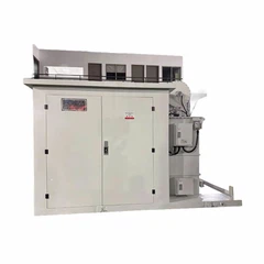
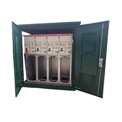
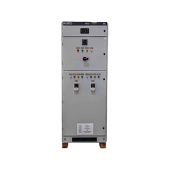
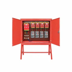
Our company offers a variety of power distribution cabinets, including Motor Control Cabinet, Outdoor Power Distribution Room, and Industrial Power Distribution Box.
In motor control cabinets, where there are often multiple motors with inductive loads, capacitor banks are commonly used for power factor correction. By installing capacitor banks in parallel with the motors, we can reduce the reactive power and improve the overall power factor of the cabinet.
For outdoor power distribution rooms, which may be exposed to harsh environmental conditions, SVCs or APFC modules are more suitable. These devices can provide reliable power factor correction and can withstand the effects of temperature, humidity, and dust.
In industrial power distribution boxes, which are used to distribute power to various industrial equipment, a combination of capacitor banks and APFC modules can be used. Capacitor banks can handle the bulk of the reactive power, while APFC modules can provide fine - tuning and improve the power factor of the electronic loads.
Conclusion
Power factor correction is an important aspect of power distribution cabinet operation. By using methods such as capacitor banks, synchronous condensers, SVCs, and APFC, we can improve the power factor, reduce energy losses, and lower electricity bills. As a power distribution cabinet supplier, we are committed to providing our customers with high - quality products and solutions for power factor correction.
If you are interested in purchasing power distribution cabinets or need more information about power factor correction, please feel free to contact us for a detailed discussion. We look forward to working with you to meet your power distribution needs.
References
- Chapman, S. J. (2012). Electric Machinery Fundamentals. McGraw - Hill.
- Grainger, J. J., & Stevenson, W. D. (1994). Power System Analysis. McGraw - Hill.
- Nasar, S. A., & Unnewehr, L. E. (1996). Electric Machines and Transformers. Prentice Hall.
Send Inquiry