What is the working principle of low-voltage switchgear?
Mar 01, 2026
Leave a message
The working principle of low-voltage switchgear is mainly based on electrical control and protection technology. By integrating components such as circuit breakers, contactors, and transformers, it realizes the functions of power distribution, control, and protection for low-voltage power distribution systems. Its core logic can be summarized as: Power input → Branch distribution → Load control → Fault protection. The following analysis will focus on three dimensions: technical principle, structural composition, and operating logic:
Technical Principle: Graded Protection and Selective Disconnection
The design of low-voltage switchgear follows the IEC 61439 standard. Through the coordination of main switches (such as frame circuit breakers) and branch switches (such as molded case circuit breakers), three levels of protection are achieved:
Incoming Line Protection: The main switch is equipped with overcurrent, short-circuit, and undervoltage release functions. When the system voltage is abnormal or the current exceeds the rated value (such as a 1000A busbar rated current scenario), the power supply is disconnected within 0.1 seconds to prevent equipment damage.
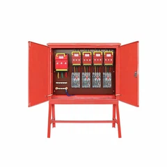
Outgoing Line Protection: Branch switches are configured with independent protection parameters for specific loads (e.g., motors, lighting). For example, if a circuit's rated current is 200A, the branch switch will trip when the load current exceeds 220A (110% of the rated value), preventing the fault from spreading.
Leakage Current Protection: Leakage current (typically ≤30mA) is detected by a residual current transformer. When the leakage value exceeds a set threshold, the circuit is cut off within 0.04 seconds, ensuring personal safety.
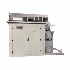
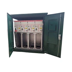
Structural Composition: Modular Design and Functional Zoning: The low-voltage switchgear adopts a cabinet-style structure (e.g., a stainless steel enclosure with IP40 protection rating). The interior is divided into four functional areas:
Busline System: Located at the top of the cabinet, it uses copper or aluminum busbars to transmit power, with a rated current of up to 1000A. It is fixed by insulators to ensure no breakdown under a 10kV withstand voltage test.
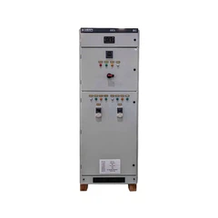
Circuit Breaker Compartment: This compartment houses the main switch and branch switches. The welded connection structure (as mentioned in the parameters) enhances mechanical strength and reduces contact resistance.
Circuit Breaker Compartment: This compartment houses the main switch and branch switches. Cable compartment: Features pre-drilled cable entry holes at the bottom, supporting either top or bottom entry to accommodate different power distribution room layouts (e.g., bottom entry is commonly used in secondary power distribution rooms).
Secondary circuit compartment: Integrates control relays, instruments, and other components, connected via terminal blocks to achieve remote monitoring and automated control.
Send Inquiry