

How does a Power Factor Controller Panel measure the power factor?
Sep 15, 2026
Leave a message
How does a Power Factor Controller Panel measure the power factor?
As a supplier of Power Factor Controller Panels, I often encounter customers who are curious about how these panels measure the power factor. Understanding this process is crucial for anyone involved in electrical systems, as it helps in optimizing energy usage and reducing costs. In this blog post, I will explain the working principle of power factor measurement in a Power Factor Controller Panel.
What is Power Factor?
Before delving into the measurement process, it's important to understand what power factor is. Power factor is a measure of how effectively electrical power is being used in a circuit. It is the ratio of real power (measured in kilowatts, kW) to apparent power (measured in kilovolt - amperes, kVA). A power factor of 1 (or 100%) indicates that all the electrical power supplied to the circuit is being used effectively, while a lower power factor means that a significant portion of the power is being wasted.
The Role of a Power Factor Controller Panel
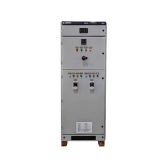
A Power Factor Controller Panel is designed to monitor and control the power factor of an electrical system. It continuously measures the power factor and takes corrective actions to improve it. By maintaining a high power factor, the panel helps in reducing energy losses, improving the efficiency of electrical equipment, and lowering electricity bills.
Measuring the Power Factor in a Power Factor Controller Panel
The measurement of power factor in a Power Factor Controller Panel involves several steps and components. Here's a detailed look at the process:
1. Voltage and Current Sensing
The first step in measuring the power factor is to sense the voltage and current in the electrical circuit. The panel is equipped with voltage and current transformers that are connected to the main electrical supply. These transformers step down the high - voltage and high - current levels to a safe and measurable range.
The voltage transformer (VT) measures the voltage across the circuit, while the current transformer (CT) measures the current flowing through the circuit. The signals from the VT and CT are then sent to the power factor controller unit within the panel.
2. Phase Angle Measurement
The power factor is related to the phase angle between the voltage and current waveforms. In an ideal electrical circuit with a power factor of 1, the voltage and current waveforms are in phase. However, in real - world circuits, there is often a phase difference between the two waveforms due to the presence of inductive or capacitive loads.


The power factor controller unit uses advanced electronics to measure the phase angle between the voltage and current signals. It analyzes the time difference between the zero - crossing points of the voltage and current waveforms. By determining the phase angle, the controller can calculate the power factor using the following formula:
Power Factor (PF)= cos(θ)
where θ is the phase angle between the voltage and current waveforms.
3. Calculation of Real and Apparent Power
In addition to measuring the phase angle, the power factor controller also calculates the real power (P) and apparent power (S) in the circuit. Real power is the power that is actually consumed by the load and is responsible for doing useful work, such as running motors or lighting. Apparent power is the total power supplied to the circuit and is the product of the voltage and current magnitudes.
The controller uses the measured voltage and current values, along with the phase angle, to calculate the real and apparent power using the following formulas:
Real Power (P)= V × I × cos(θ)
Apparent Power (S)= V × I
where V is the voltage, I is the current, and θ is the phase angle.
4. Display and Monitoring
Once the power factor, real power, and apparent power are calculated, the power factor controller panel displays these values on a digital display. This allows operators to monitor the power factor in real - time and take appropriate actions if the power factor falls below a certain threshold.
The panel may also be equipped with alarms that notify operators when the power factor drops below a pre - set level. This helps in ensuring that the electrical system is operating efficiently and that any issues are addressed promptly.
Importance of Accurate Power Factor Measurement
Accurate power factor measurement is essential for several reasons. Firstly, it helps in identifying the presence of inductive or capacitive loads in the electrical system. Inductive loads, such as motors and transformers, tend to have a low power factor, which can lead to increased energy losses and higher electricity bills. By measuring the power factor, operators can take steps to correct the power factor, such as installing power factor correction capacitors.
Secondly, accurate power factor measurement is important for complying with electricity utility regulations. Many utilities charge penalties for low power factor, as it puts additional stress on the electrical grid. By maintaining a high power factor, customers can avoid these penalties and reduce their overall electricity costs.
Power Factor Correction
Power factor correction is the process of improving the power factor of an electrical system. One of the most common methods of power factor correction is the use of power factor correction capacitors. These capacitors are connected in parallel with the inductive loads in the circuit. They generate reactive power that counteracts the reactive power consumed by the inductive loads, thereby improving the power factor.
A Power Factor Controller Panel plays a crucial role in power factor correction. It continuously monitors the power factor and controls the switching of the power factor correction capacitors. When the power factor drops below a certain level, the controller activates the capacitors to inject reactive power into the circuit. When the power factor improves, the controller deactivates the capacitors to prevent over - correction.
Related Products
If you are interested in power factor correction and electrical systems, you may also be interested in our Power Factor Correction Panel. This panel is designed to provide efficient power factor correction and improve the overall performance of your electrical system.
We also offer Low Tension Switchgear and Mns Low Voltage Switchgear that are essential components of any electrical distribution system. These switchgears provide protection, control, and isolation for electrical circuits.
Contact Us for Purchase and Consultation
If you are looking to purchase a Power Factor Controller Panel or have any questions about power factor measurement and correction, we are here to help. Our team of experts can provide you with detailed information about our products and services, and assist you in selecting the right solution for your specific needs.
Whether you are a small business or a large industrial facility, optimizing your power factor can lead to significant cost savings and improved energy efficiency. Contact us today to start a discussion about how our Power Factor Controller Panels can benefit your electrical system.
References
- Electric Power Systems: Analysis and Control by Prabha Kundur
- Electrical Engineering Principles and Applications by Allan R. Hambley
- Power System Analysis and Design by J. Duncan Glover, Mulukutla S. Sarma, and Thomas J. Overbye
Send Inquiry